In this chapter, we are going to summarize the knowledge learnt from the previous chapters. We shall be taking up an exercise to model a Robot in Maya. The process is simple and is designed to help a beginner to understand the concepts of modeling in Maya.
Our Robot shall be based on a set of primitives. We shall go through the usage of transform tools and few other modeling techniques.
To start, open a new scene in Maya using File>New Scene.
Select Modeling Menu set from the status line or press F3 as the keyboard shortcut.
We shall start the modeling by creating a polygon cylinder primitive by accessing Create>Polygon Primitives>Cylinder.
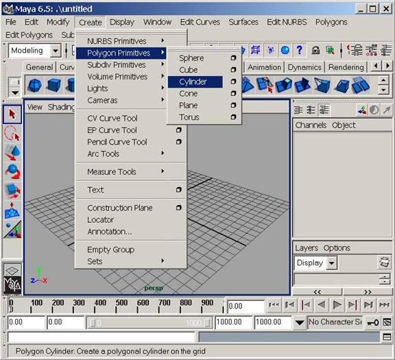
Fig 10-1
Now we need to switch to the component mode in order to make changes to the primitive cylinder that we just made.
Press F8 to go to the component mode and select the point option.
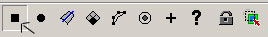
Fig 10-2 Component Mode options
Select the top vertices as shown yellow in the given figure. Use the Scale transform tool and using the middle yellow cube, click and drag the mouse to increase the scale.
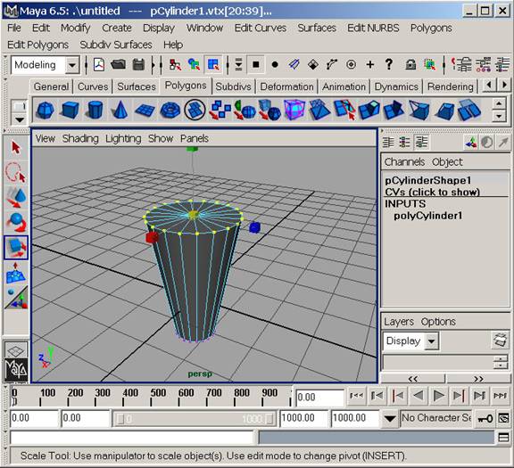
Fig 10-3 Editing the primitive in component mode
Let us call this object that we modeled, “limb unit”. We shall be using this object by making copies of it and resizing them and then fixing at the required locations. This unit will form the limbs of our Robot. You can use the Move Transform tool, and Rotate Transform tool to position the object in the scene.
If you are already in component mode, press F8 to come out of it. First of all start by creating a copy of the existing object by pressing keyboard shortcut Ctrl D. Use the Move transform tool to move the new created object to a side.
Use the Scale tool to downsize the newly created limb unit and then use the Move tool and rotate tool to get both of the objects in the shape, orientation and position as shown in the given figure.
Fig 10_4
Use the Copy, move, scale and rotate tools to make 4 more limb units out of the original one and resize, position and orient them to form the 3 fingers and 1 thumb of the Robot.
Using the similar techniques explained above, this time create a polygon sphere primitive and use its copies to form the joints of the limbs as shown in the given figure.
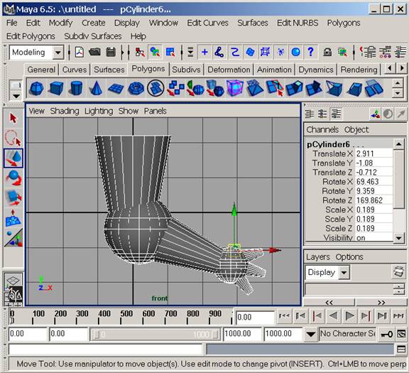
Fig 10-5
Next, we need to make another similar limb structure as shown in Fig10-5 in order to form the other arm. You can rotate both the arms to be a bit inclined outwards from the elbows. Match the orientation and position of the two arms with the one shown in the following figure.
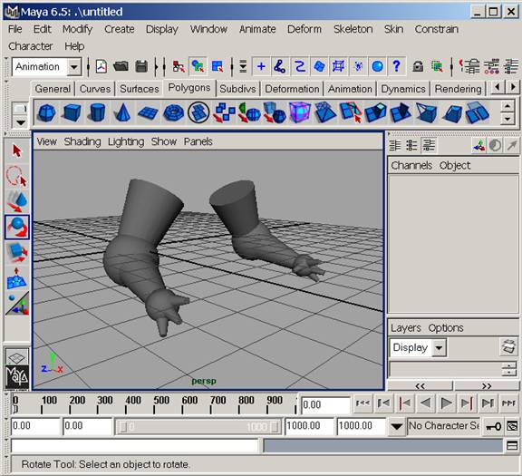
Fig 10-6
Now, that we have both the arms of the Robot ready, we are not far from developing the complete humanoid. We can continue developing the legs of the robot in exactly the similar manner that we have used till now. After completing the legs, the robot will somewhat look like in the figure 10-7. However, at this point of time you may want to use your own creativity and try different looks for the Robot.
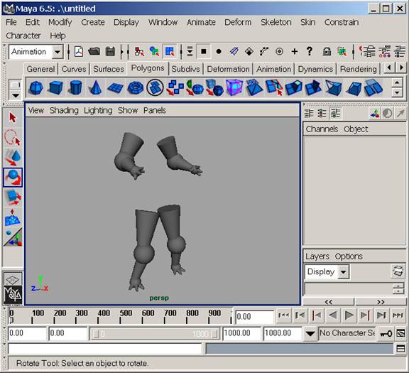
Fig 10-7
In the next step we shall use few more spheres and a cylinder to make the torso of the robot as shown in the next figure.
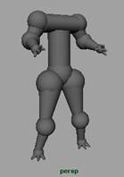
Fig 10-8
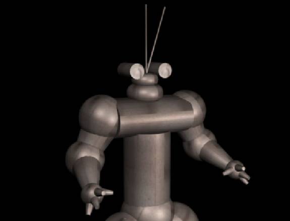
The process had been pretty simple so far. We have been using just two basic polygon primitives i.e., cylinder and a sphere. Now, lets make use of another primitive i.e., Torus. Create a Torus from the create Menu. Resize and position it to form the elements of the Neck. You can go a step ahead by using the cylinder primitives to form the camera like structure that are substitute for the eyes in our Robot. A real small radius cylinders can be used to form something that can act as an antenna receptor. The final modeled structure of the Robot is shown in this rendered image.
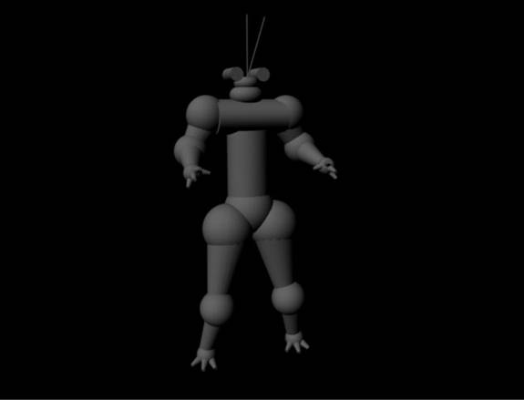
Fig 10-9 The complete model
Now, we shall texture this Robot. Lets start by opening the Hypershade , Windows>Rendering Editors>Hypershade. Select the Blinn material and name it to Robotexture.
Create a Blinn Material - Create (on the Hypershade menu)...>Materials...>...Blinn, or use the side bar. Double-click the new material to open the attribute editor. Change the material name to Robo_Blinn or so. Click the box next to the color slider, a new option window opens. Choose Normal and click File to assign a bitmap as the material color.
Fig 10-11
You can select any metal texture image for the purpose. I have included one that we are going to use now with the accompanying source file for this tutorial.
Repeat the procedure to assign the same file to the specular color. Now, on the perspective view shading menu choose smooth shade all and turn on Hardware texturing.
Select the robot, shift select the Material in the Hypershade, right-click-it and "assign material to selection". Your robot is now textured.
Now, before we render out our robot, we need to setup a simple light rig for the purpose.
Create a point light Create>Lights>Point Light, open the attribute editor (control-a), expand the shadows options and turn depth map shadows on. Press 7 to view the lighting in the view port, duplicate the light 2 or 3 times and move them around the robot until you get the desired look.
Open the render globals window from Window>Rendering Editors>Render Globals. Select the anti aliasing quality to production. Ready to go, Render out the scene.
Our Robot shall be based on a set of primitives. We shall go through the usage of transform tools and few other modeling techniques.
To start, open a new scene in Maya using File>New Scene.
Select Modeling Menu set from the status line or press F3 as the keyboard shortcut.
We shall start the modeling by creating a polygon cylinder primitive by accessing Create>Polygon Primitives>Cylinder.
Fig 10-1
Now we need to switch to the component mode in order to make changes to the primitive cylinder that we just made.
Press F8 to go to the component mode and select the point option.
Fig 10-2 Component Mode options
Select the top vertices as shown yellow in the given figure. Use the Scale transform tool and using the middle yellow cube, click and drag the mouse to increase the scale.
Fig 10-3 Editing the primitive in component mode
Let us call this object that we modeled, “limb unit”. We shall be using this object by making copies of it and resizing them and then fixing at the required locations. This unit will form the limbs of our Robot. You can use the Move Transform tool, and Rotate Transform tool to position the object in the scene.
If you are already in component mode, press F8 to come out of it. First of all start by creating a copy of the existing object by pressing keyboard shortcut Ctrl D. Use the Move transform tool to move the new created object to a side.
Use the Scale tool to downsize the newly created limb unit and then use the Move tool and rotate tool to get both of the objects in the shape, orientation and position as shown in the given figure.
Fig 10_4
Use the Copy, move, scale and rotate tools to make 4 more limb units out of the original one and resize, position and orient them to form the 3 fingers and 1 thumb of the Robot.
Using the similar techniques explained above, this time create a polygon sphere primitive and use its copies to form the joints of the limbs as shown in the given figure.
Fig 10-5
Next, we need to make another similar limb structure as shown in Fig10-5 in order to form the other arm. You can rotate both the arms to be a bit inclined outwards from the elbows. Match the orientation and position of the two arms with the one shown in the following figure.
Fig 10-6
Now, that we have both the arms of the Robot ready, we are not far from developing the complete humanoid. We can continue developing the legs of the robot in exactly the similar manner that we have used till now. After completing the legs, the robot will somewhat look like in the figure 10-7. However, at this point of time you may want to use your own creativity and try different looks for the Robot.
Fig 10-7
In the next step we shall use few more spheres and a cylinder to make the torso of the robot as shown in the next figure.
Fig 10-8
The process had been pretty simple so far. We have been using just two basic polygon primitives i.e., cylinder and a sphere. Now, lets make use of another primitive i.e., Torus. Create a Torus from the create Menu. Resize and position it to form the elements of the Neck. You can go a step ahead by using the cylinder primitives to form the camera like structure that are substitute for the eyes in our Robot. A real small radius cylinders can be used to form something that can act as an antenna receptor. The final modeled structure of the Robot is shown in this rendered image.
Fig 10-9 The complete model
Now, we shall texture this Robot. Lets start by opening the Hypershade , Windows>Rendering Editors>Hypershade. Select the Blinn material and name it to Robotexture.
Create a Blinn Material - Create (on the Hypershade menu)...>Materials...>...Blinn, or use the side bar. Double-click the new material to open the attribute editor. Change the material name to Robo_Blinn or so. Click the box next to the color slider, a new option window opens. Choose Normal and click File to assign a bitmap as the material color.
Fig 10-11
You can select any metal texture image for the purpose. I have included one that we are going to use now with the accompanying source file for this tutorial.
Repeat the procedure to assign the same file to the specular color. Now, on the perspective view shading menu choose smooth shade all and turn on Hardware texturing.
Select the robot, shift select the Material in the Hypershade, right-click-it and "assign material to selection". Your robot is now textured.
Now, before we render out our robot, we need to setup a simple light rig for the purpose.
Create a point light Create>Lights>Point Light, open the attribute editor (control-a), expand the shadows options and turn depth map shadows on. Press 7 to view the lighting in the view port, duplicate the light 2 or 3 times and move them around the robot until you get the desired look.
Open the render globals window from Window>Rendering Editors>Render Globals. Select the anti aliasing quality to production. Ready to go, Render out the scene.


0 comments:
Post a Comment